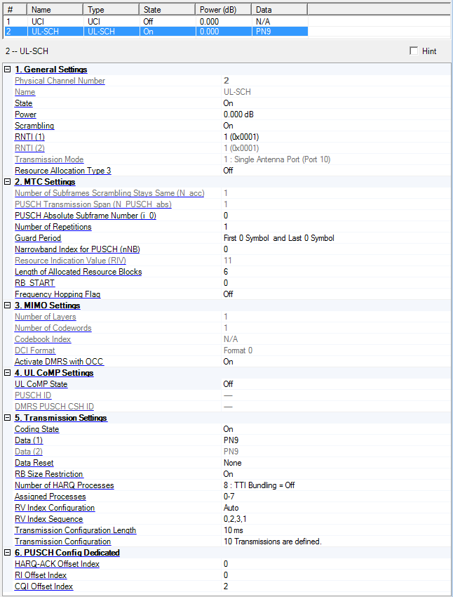
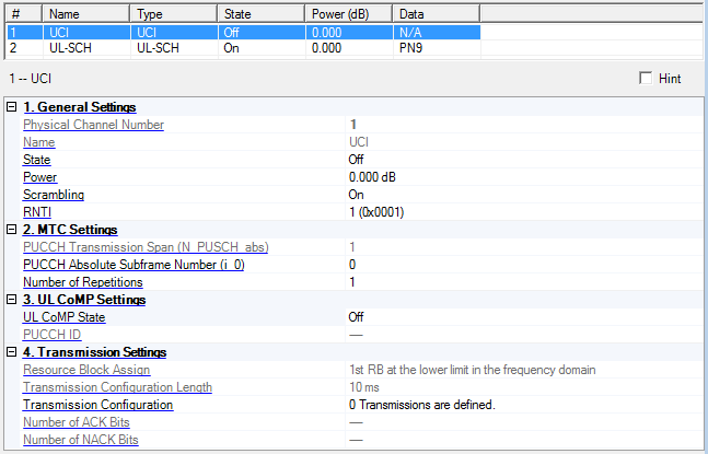
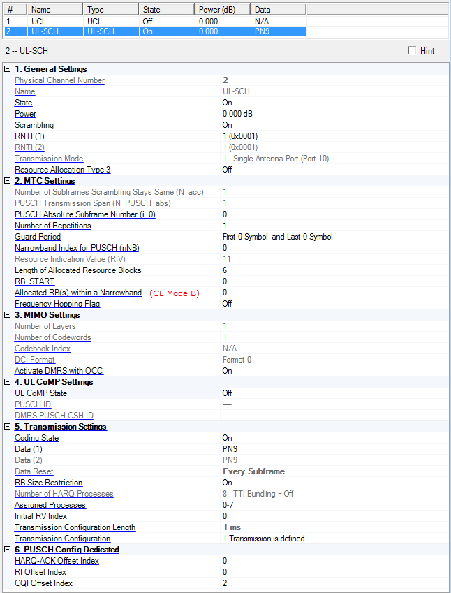
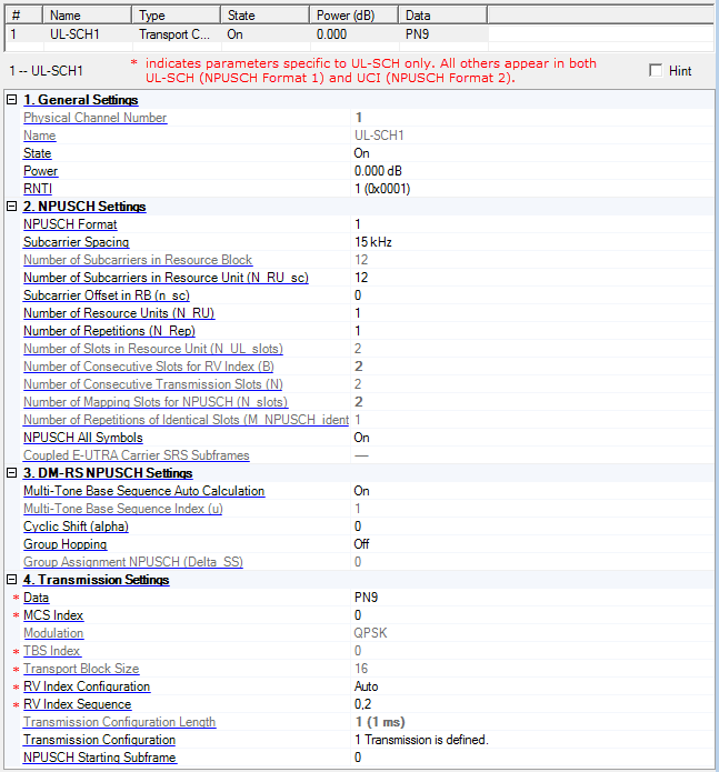
Displays the identifying number of the selected channel.
Displays the name of the selected channel.
UCI = Uplink Control Information
UL-SCH = Uplink Shared Channel
Displays the name of the selected channel.
UL-SCH = Uplink Shared Channel (NPUSCH Format 1)
UCI = Uplink Control Information (NPUSCH Format 2)
Choice: Off | On
Default: Off
Double-click or use the drop-down menu to turn the selected channel off or on.
UCI Parameters: If the total number of antennas is set to 4 under the Uplink Cell Parameters, the state is set to off and is read only.
Range: -60.000 to 20.000 dB
Default: 0.000 dB
Enter a power level in dB for the selected channel. See Output Power Calculation (Uplink) for a description of how the software applies your power setting.
Choice: Off | On
Default: On
Double-click or use the drop-down menu to turn scrambling for the physical channel on or off.
Range: 0 to 65535 (0x0000 to 0xFFFF)
Default: 1 (0x0001)
Enter the Radio Network Temporary Identifier (RNTI) for the corresponding PUCCH transmission.
The input method can be in decimal format or hexadecimal format.
Example: The decimal input "15" is displayed as "15 (0x000F)" and the hexadecimal input "0xf" is displayed as "15 (0x000F)".
See 3GPP TS 36.211 and 36.321, for more information.
Range: 0 to 65535 (0x0000 to 0xFFFF)
Default: 1 (0x0001)
Enter the Radio Network Temporary Identifier (RNTI) for transport block 1 (codeword 0).
The input method can be in decimal format or hexadecimal format.
Example: The decimal input "15" is displayed as "15 (0x000F)" and the hexadecimal input "0xf" is displayed as "15 (0x000F)".
See 3GPP TS 36.211 and 36.321, for more information.
Range: 0 to 65535 (0x0000 to 0xFFFF)
Default: 1 (0x0001)
Enter the Radio Network Temporary Identifier (RNTI) for transport block 2 (codeword 1). The input method can be allowed the decimal format or hexadecimal format.
This parameter is available only when Number of Codewords is 2. Otherwise disable and read-only.
Example) The decimal input "15" is displayed as "15 (0x000F)" and the hexadecimal input "0xf" is displayed as "15 (0x000F)".
See 3GPP TS 36.211 5.3.1 and 36.321 7.1, for more information.
Range: 0 to 65535 (0x0000 to 0xFFFF)
Default: 1 (0x0001)
Enter the Radio Network Temporary Identifier (RNTI) for transport block 1 (codeword 0).
The input method can be allowed the decimal format or hexadecimal format.
Example) The decimal input "15" is displayed as "15 (0x000F)" and the hexadecimal input "0xf" is displayed as "15 (0x000F)".
See 3GPP TS 36.211 10.1.3.1 and 36.321 7.1, for more information.
Displays the transmission mode for the corresponding PUSCH transmission.
The Transmission Mode is dependent on the Total Number of Antennas used.
Transmission Mode 1 is used for single antenna transmission and Transmission Mode 2 is used for multi-antenna transmission.
1 : Single Antenna Port (Port 10) Default when 1 Antenna is selected under Uplink Cell Parameters
2 : Single Antenna Port (Port 10) / Closed Loop Spatial Multiplexing Default when 1 or 4 Antenna(s) is(are) selected under Uplink Cell Parameters
See 3GPP TS 36.211 and 36.213, for more information.
Choice: On | Off
Default: Off
Double-click or use the drop-down menu to turn the resource allocation type 3 state on or off for the channel.
When this parameter is changed to on, System Bandwidth is set to 10 MHz or 20 MHz, Cyclic Prefix is set to Normal, PUSCH Auto-calculate per-slot params is set to on, and Number of HARQ Processes is set to 8, automatically.
When Transmission BW is changed to a value other than 10 MHz or 20 MHz, Cyclic Prefix is changed to Extended, PUSCH Auto-calculate per-slot params is changed to off, or Number of HARQ Processes is changed to a value other than 8, this parameter is automatically set to off.
This parameter is active only when UE Type is Non-BL/CE.
This parameter does not affect the parameter setting on the FRC Wizard window.
See 3GPP TS 36.213 8.1.4 for more information.
Displays the number of consecutive absolute subframes over which the scrambling sequence stays the same (N_acc).
1: CE Mode A
4: CE Mode B
See 3GPP TS 36.211 for more information.
Displays the number of consecutive subframes including invalid subframes where the UE postpones the PUSCH transmission for BL/CE UE.
This parameter is used only when UE Type is set to BL/CE.
See 3GPP TS 36.211 for more information.
Range: 0 to 10239
Default: 0
Enter the absolute subframe number of the first UL subframe intended for carrying the PUSCH.
This parameter is used only when UE Type is set to BL/CE.
This parameter should be set to a valid subframe number defined by Valid Subframes. Otherwise, an error occurs during the generation.
See 3GPP TS 36.211 for more information.
Range:
1 | 2 | 4 | 8 | 16 | 32: CE Mode A
4 | 8 | 16 | 32: CE Mode B
Default:
1: CE Mode A
4: CE Mode B
Double-click or use the drop-down menu to select the number of repetitions.
This parameter is used only when UE Type is set to BL/CE.
See 3GPP TS 36.211 for more information.
Range:
1 | 2 | 4 | 8 | 16 | 32 for CE Mode A
1 | 4 | 8 | 16 | 32 | 64 | 128 | 192 | 256 | 384 | 512 | 768 | 1024 | 1536 | 2048 for CE Mode B
Default: 1
Double-click or use the drop-down menu to select the number of repetitions.
This parameter is used only when UE Type is set to BL/CE.
See 3GPP TS 36.213 for more information.
Choice: First 0 Symbol and Last 0 Symbol | First 0 Symbol and Last 2 Symbols | First 1 Symbol and Last 0 Symbol | First 1 Symbol and Last 2 Symbols | First 2 Symbols and Last 0 Symbol | First 2 Symbols and Last 2 Symbols
Default: First 0 Symbol and Last 0 Symbol
Double-click or use the drop-down menu to select the guard period.
This parameter is used only when UE Type is set to BL/CE.
See 3GPP TS 36.211 for more information
Range:
1.4 MHz: 0
3 MHz: 0 to 1
5 MHz: 0 to 3
10 MHz: 0 to 7
15 MHz: 0 to 11
20 MHz: 0 to 15
Default: 0
Enter the narrowband index. Available number of this parameter is determined by the system bandwidth setting defined in the Uplink node.
This parameter is used only when UE Type is set to BL/CE.
See 3GPP TS 36.211 and 36.212 for more information.
Displays the resource indication value (RIV).
This parameter is coupled to RB_START and Length of allocated resource blocks.
This parameter appears only when CE Mode is set to Mode A.
This parameter is used only when UE Type is set to BL/CE.
See 3GPP TS 36.213 for more information.
Range: 1 to 6
Default: 6
Enter the length in terms of contiguously allocated resource blocks (L_CRBs).
This parameter appears only when CE Mode is set to Mode A.
This parameter is coupled to RB_START.
This parameter is used only when UE Type is set to BL/CE.
See 3GPP TS 36.213 for more information.
Range: 0 to 5
Default: 0
Enter the start resource block (RB_START).
This parameter appears only when CE Mode is set to Mode A.
This parameter is coupled to L_CRBs.
This parameter is used only when UE Type is set to BL/CE.
See 3GPP TS 36.213 for more information.
Choice: 0 | 1 | 2 | 3 | 4 | 5 | 0 and 1 | 2 and 3
Default: 0
Double-click or use the drop-down menu to select the allocated RB(s) within a narrowband.
This parameter appears only when CE Mode is set to Mode B.
This parameter is used only when UE Type is set to BL/CE.
See 3GPP TS 36.213 for more information.
Choice: On | Off
Default: Off
Double-click or use the drop-down menu to turn PUSCH frequency hopping for BL/CE UE on or off.
This parameter is used only when UE Type is set to BL/CE.
See 3GPP TS 36.213 for more information
Displays the number of consecutive subframes including invalid subframes where the UE postpones the PUCCH transmission for BL/CE UE.
This parameter is used only when UE Type is set to BL/CE.
See 3GPP TS 36.211 for more information.
Range: 0 to 10239
Default: 0
Enter the absolute subframe number of the first UL subframe intended for carrying the PUCCH.
This parameter is used only when UE Type is set to BL/CE.
This parameter should be set to a valid subframe number defined by Valid Subframes. Otherwise, an error occurs during the generation.
See 3GPP TS 36.211 for more information.
Choice: 1 | 2
Default: 1
Use the drop-down menu to set NPUSCH Format Type.
Format 1: Used for data transmission. (UL-SCH)
Format 2: Used for control information transmission. (UCI)
See 3GPP TS 36.211 10.1.2.3 and 10.1.3 for more information.
Choice: 15 KHz | 3.75 KHz
Default: 15 KHz
Double-click or use the drop-down menu to set Subcarrier Spacing.
See 3GPP TS 36.211 10.1.2.1 for more information.
Displays Number of Subcarriers in Resource Block.
See 3GPP TS 36.211 10.1.2.1 for more information.
Choice: 1 | 3 | 6 | 12
Default: 12
Double-click or use the drop-down menu to set Number of Subcarriers in Resource Unit (N_RU_sc).
This parameter is only selectable when NPUSCH Format 1 and Subcarrier Spacing is 15 kHz. Otherwise automatically decided with read-only.
See 3GPP TS 36.211 10.1.2.3 for more information.
Choice:
0 (N_RU_sc = 12 and Subcarrier Spacing = 15 kHz)
0 | 6 (N_RU_sc = 6 and Subcarrier Spacing = 15 kHz)
0 | 3 | 6 | 9 (N_RU_sc = 3 and Subcarrier Spacing = 15 kHz)
0 to 11 (NN_RU_sc = 1 and Subcarrier Spacing = 15 kHz)
0 to 47 (Subcarrier Spacing = 3.75 kHz)
Default: 0
Double-click or use the drop-down menu to set Subcarrier Offset in RB (n_sc).
See 3GPP TS 36.213 16.5.1.1 for more information.
Choice: 1 | 2 | 3 | 4 | 5 | 6 | 8 | 10
Default: 0
Double-click or use the drop-down menu to set Number of Resource Units for NPUSCH (N_RU)
See 3GPP TS 36.211 10.1.3.6 and 36.213 16.5.1.1 for more information.
Choice: 1 | 2 | 4 | 8 | 16 | 32 | 64 | 128
Default: 0
Double-click or use the drop-down menu to set Number of Repetitions (N_Rep) for NPUSCH.
See 3GPP TS 36.211 10.1.3.6 and 36.213 16.5.1.1 for more information.
Displays Number of Slots in Resource Unit (N_UL_slots).
See 3GPP TS 36.211 10.1.2.2 for more information.
Displays Number of Consecutive Slots for RV Index (B).
See 3GPP TS 36.213 16.5.1.2 for more information.
Displays Number of Consecutive Transmission Slots (N).
See 3GPP TS 36.213 16.5.1.2 for more information.
Displays Number of Mapping Slots for NPUSCH (N_slots).
See 3GPP TS 36.211 10.1.3.6 for more information.
Displays Number of Repetitions of Identical Slots for NPUSCH (M_NPUSCH_identical).
See 3GPP TS 36.211 10.1.3.6 for more information.
Choice: Off | On
Default: On
This parameter is active only when Operation Mode in the Uplink node is In-Band. Otherwise automatically set to on, and read-only.
When this parameter is set to off, the resource elements in SC-FDMA symbols overlapped with a symbol configured with SRS according to SRS Subframe Configuration shall be counted in the NPUSCH mapping but these resource elements are not used for transmission of the NPUSCH.
When this parameter is set to on, all NB-IoT symbols for NPUSCH are transmitted.
See 3GPP TS 36.211 10.1.3.6, and 36.331 6.7.3.2 for more information.
Displays the coupled E-UTRA carrier SRS subframes.
This parameter is visible only when Operation Mode in the Uplink node is In-Band.
If the coupled E-UTRA Carrier is off or SRS State is off, “---” is displayed as SRS subframes have no values.
See 3GPP TS 36.211 10.1.3.6, and 36.331 6.7.3.2 for more information.
Choice: (Dependent on the Total Number of Antennas.)
1 (1 Antenna case) Default =1 when 1 Antenna is selected under Uplink Cell Parameters
1 | 2 (2 Antennas case) Default =2 when 2 Antennas are selected under Uplink Cell Parameters
1 | 2 | 3 | 4 (4 Antennas case) Default =4 when 4 Antennas are selected under Uplink Cell Parameters
Double-click or use the drop-down menu to select the number of layers for the corresponding PUSCH transmission. The number of layers is less than or equal to the number of antennas.
Choice: Dependent on the Total Number of Antennas and Number of Layers.)
1 (1 Antenna case) Default when 1 Antenna is selected under Uplink Cell Parameters
1 (2 Antennas, 1 Layer case)
2 (2 Antennas, 2 Layers case) Default when 2 Antennas are selected under Uplink Cell Parameters
1 (4 Antennas, 1 Layer case)
1 | 2 (4 Antennas, 2 Layers case) Default =2 when 4 Antennas are selected under Uplink Cell Parameters
2 (4 Antennas, 3 Layers case)
2 (4 Antennas, 4 Layers case)
Default: 1
Double-click or use the drop-down menu to select the number of codewords for the corresponding PUSCH transmission.
See 3GPP TS 36.211, 36.212 and 36.213, for more information.
Range: (Dependent on the Total Number of Antennas, Number of Layers, and DCI Format.)
N/A (DCI Format 0 case) Default when 1 Antenna is selected under Uplink Cell Parameters or when DCI Format is set to Format 0.
0 to 5 (2 Antennas, 1 Layer case)
0 (2 Antennas, 2 Layers case) Default when 2 Antennas are selected under Uplink Cell Parameters
0 to 23 (4 Antennas, 1 Layer case)
0 to 15 (4 Antennas, 2 Layers case) Default when 4 Antennas are selected under Uplink Cell Parameters
0 to 11 (4 Antennas, 3 Layers case)
0 (4 Antennas, 4 Layers case)
Enter the codebook index for the corresponding PUSCH transmission.
In case of DCI Format 0, N/A is displayed.
See 3GPP TS 36.211, 36.212 and 36.213, for more information.
Choice: (Dependent on the Total Number of Antennas, Number of Layers and Number of Codewords.)
Format 0 (1 Antenna case) Default when 1 Antenna is selected under Uplink Cell Parameters
Format 0 | Format 4 (2 Antennas, 1 Layer, 1 Codeword case) Default =4 when 2 Antennas are selected under Uplink Cell Parameters
Format 0 | Format 4 (4 Antennas, 1 Layer, 1 Codeword case) Default =4 when 4 Antennas are selected under Uplink Cell Parameters
Default: Format 0
Double-click or use the drop-down menu to select the DCI Format for the corresponding PUSCH transmission.
See 3GPP TS 36.211, 36.212 and 36.213, for more information.
Choice: On | Off
Default: On
Double-click or use the drop-down menu to set the Activate-DMRS-with OCC parameter on or off for the corresponding PUSCH transmission.
See 3GPP TS 36.211 and 36.331, for more information.
Choice: Off | On
Default: On
Double-click or use the drop-down menu to turn automatic calculation for base sequence index parameter on or off.
On: Automatically calculate Base Sequence Index
Off: Manual input is available.
This parameter is only available when Number of Subcarriers in Resource Unit (N_RU_sc) is 12 or 6 or 3 (multitone). Otherwise disable with read-only.
Range: 0 to 29 (maximum value depends on Number of Subcarriers in Resource Unit)
Default: 0
Enter a value for Multi-Tone Base Sequence Index (u).
It is used for DM-RS NPUSCH when group hopping is not enable.
This parameter is only available when Multi-Tone Base Sequence Auto Calculation is Off, Number of Subcarriers in Resource Unit (N_RU_sc) is 12 or 6 or 3 (multitone) and Group Hopping is Off.
Otherwise automatically decided (multitone) or disable with read-only (singletone).
See 3GPP TS 36.211 10.1.4.1.2 for more information.
Range:
0 to 2 (N_RU_sc = 3)
0 to 3 (N_RU_sc = 6)
0 (N_RU_sc = 12)
Default: 0
Enter a value for Cyclic Shift (alpha).
This parameter is available only when Number of Subcarriers in Resource Unit (N_RU_sc) is 12, 6, or 3. Otherwise disabled and read-only.
See 3GPP TS 36.211 10.1.4.1.2 for more information.
Choice: On | Off
Default: Off
Double-click or use the drop-down menu to set Group Hopping on or off for DM-RS NPUSCH.
This parameter is only available when NPUSCH Format 1. Otherwise disable with read-only.
See 3GPP TS 36.211 10.1.4.1.3 for more information.
Range: 0 to 29
Default: 0
Enter a value for Group Assignment NPUSCH (Delta_SS).
This value is used to calculate the sequence-shift pattern for DM-RS NPUSCH.
This parameter is only available when Group Hopping is On and NPUSCH Format 1. Otherwise disable with read-only.
See 3GPP TS 36.211 10.1.4.1.3 for more information.
Choice: On | Off
Default: Off
Double-click or use the drop-down menu to turn the state on or off. PUSCH ID parameter is active only when UL CoMP State is on.
See 3GPP TS 36.211 5.5.1.5 for more information.
Choice: On | Off
Default: Off
Double-click or use the drop-down menu to turn the state on or off.
When UL CoMP State is On, PUCCH ID is available to set a value. Otherwise this parameter is not available to set a value as read-only.
See 3GPP TS 36.211 and 36.311 for more information.
Range: 0 to 509
Default: 0
Enter a value of PUSCH Identity (ID) which is used for virtual cell ID. This parameter is active only when UL CoMP State is on.
See 3GPP TS 36.211 5.5.1.5 and 36.311 6.3.2 for more information.
Range: 0 to 509
Default: 0
Enter a value of PUSCH Identity (ID) which is used for virtual cell ID. This parameter is active only when UL CoMP State is on.
See 3GPP TS 36.211 5.5.1.5 and 36.311 6.3.2 for more information.
Displays nDMRS-CSH-Identity (N_csh_DMRS_ID) parameter on Uplink node which is used for initial value of cyclic shift hopping of DMRS PUSCH pseudo random sequence generation. This parameter is active only when nDMRS-CSH-Identity Enable parameter on Uplink node is on.
See 3GPP TS 36.211 5.5.1.5 and 36.311 6.3.2 for more information.
Use the data source selection dialog box to select PN9, PN15 or user defined bits to use for the data in the transport block.
This parameter is only visible when NPUSCH Format 1.
Range:
N_RU_sc = 1: 0 to 10
N_RU_sc > 1: 0 to 13
Default: 0
Double-click or use the drop-down menu to set the MCS Index.
This parameter is visible only when NPUSCH Format is 1.
See 3GPP TS 36.213 16.5.1.2 Table 16.5.1.2-1 and 16.5.1.2-2 for more information.
Displays NPUSCH modulation type.
See 3GPP TS 36.211 10.1.3.2 for more information.
Displays NPUSCH TBS Index which is determined by MCS Index.
This parameter is only visible when NPUSCH Format 1.
See 3GPP TS 36.36.213 16.5.1.2 for more information.
Displays NPUSCH Transport Block Size which is determined by MCS Index and Number of Resource Units.
This parameter is only visible when NPUSCH Format 1.
See 3GPP TS 36.36.213 16.5.1.2 for more information.
Choice: Auto | Manual
Default: Auto
Double-click or use the drop-down menu to set the RV Index Configuration.
If the RV Index Configuration is set to Auto, the RV index is automatically set in order from the first element of RV index sequence.
If the RV Index Configuration is set to Manual, User can set RV index by manual in the UL-SCH Tx sequence window.
This parameter is only visible when NPUSCH Format 1.
RV index sequence is only visible when RV Index Configuration is Auto.
Range of sequence length: 1 to 16
Range of each value:0 or 2
Default: 0,2
Enter the numbers of individual RV Index Sequence, separated by commas.
For example, '0,2'.
Only numbers or comma inputs are allowed.The number less than or equal to 1 is rounded to 0. Others are rounded to 2.
This parameter is only visible when NPUSCH Format 1.
RV index sequence is only visible when RV Index Configuration is Auto.
See 3GPP TS 36.213 16.5.1.2 for more information.
Displays the length of each NPUSCH (UL-SCH or UCI) transmission configuration, and the inserted gap length is displayed in parenthesis.
The waveform time length is set to Waveform Generation Length, even if Transmission Configuration Length is set longer than Waveform Generation Length.
Click the  button in this cell to open the UL-SCH Tx sequence window or the UCI Tx sequence window.
Range: 0 to Waveform Generation Length - 1
Default: 0
Enter a value of NPUSCH Starting Subframe.
NPUSCH transmission is delayed from the beginning of waveform by adding gap period.
Choice: Off | On
Default: On
This parameter applies only to UL-SCH channels.
Double-click or use the drop-down menu to turn coding for the selected channel off or on.
If the Number of HARQ Processes is set to 3 or 4, the Coding State is set to On as read-only.
Use the Data Source Selection dialog box to select PN9, PN15, PN23, or User Defined Bits or user defined bits to use for the data in the transport block 1 (codeword 0).
See 3GPP TS 36.211, 36.212 and 36.213, for more information.
This parameter applies only to UL-SCH channels.
Use the Data Source Selection dialog box to select PN9, PN15, PN23, or User Defined Bits or user defined bits to use for the data in the transport block 2 (codeword 1).
See 3GPP TS 36.211, 36.212 and 36.213, for more information.
Choice: None | Every Subframe
Default: None
Sets the data reset method for UL-SCH.
None: the transport data is continuously repeated seed data which is specified by Data parameter. The transport data is not reset till end of waveform.
Every Subframe: the transport data is reset at the start of each subframe.
If Number of HARQ Processes is 3 or 4, Data Reset is set to None as read-only.
If UE Type is BL/CE, Data Reset is set to Every Subframe as read-only.
For eMTC Uplink CC, this parameter is set to Every Subframe first as an exception.
Choice: On | Off
Default: On
Double-click or use the drop-down menu to turn the PUSCH Resource Block Size Restriction on or off.
If it is On, PUSCH Resource Block Size is restricted equal to (2^(a*2)) * (2^(b*3)) * (2^(c*5)) or less than RB UL max. (a, b, c is non-negative integer).
This resource restriction is according to the 3GPP standard specification.
Otherwise it is just equal or less than RB UL max. (RB UL max is system RB size)
See 3GPP TS 36.211 for more information.
Choice: 3 | 4 | 8
Default: 8
Double-click or use the drop-down menu to select the number of HARQ processes.
This value determines the number of available hybrid automatic repeat request (HARQ) processes and defines the interval (number of subframes) between retransmissions.
Use the Assigned Processes parameter to enable HARQ processes.
3: TTI Bundling = On and e-HARQ-Pattern = On
4: TTI Bundling = On and e-HARQ-Pattern = Off
8: TTI Bundling = Off
If this parameter is set to 3 or 4, TTI Bundling is set to on (Bundling operation).
If this parameter is set to 8, TTI Bundling is set to off (Normal operation).
Click the button in the Transmission Configuration parameter to view the enabled HARQ processes in the UL-SCH Tx sequence window.
If UE Type is BL/CE, this parameter is set to 8 and read-only.
This parameter is automatically set to 8 when Resource Allocation Type 3 is changed to on.
Resource Allocation Type 3 is automatically set to off when this parameter is changed to a value other than 8.
See 3GPP TS 36.213, 36.321 and 36.311 for more information.
Range: 0 to (number defined in Number of HARQ Processes)
Default: 0 to 7
This parameter applies only to UL-SCH channels.
Enter the numbers of individual HARQ processes, separated by commas (for example, 1,2,3) or a range of HARQ processes ( for example, 1-3) to enable specific HARQ processes. The number of available HARQ processes is defined in the Number of HARQ Processes cell.
Your setting is displayed in the UL-SCH Tx sequence window (see Transmission Configuration).
Range: 0 to 3
Default: 0
Enter the initial RV index for BL/CE UE.
This parameter appears only when UE Type is set to BL/CE.
When CE Mode is set to Mode B, this parameter is set to 0 as read-only.
See 3GPP TS 36.213 for more information.
Choice: Auto | Manual
Default: Auto
Double-click or use the drop-down menu to set the RV Index Configuration.
If the RV Index Configuration is set to Auto, the RV index is automatically set in order from the first element of RV index sequence.
If the RV Index Configuration is set to Manual, you can set RV index manually in the UL-SCH Tx sequence window.
If the Number of HARQ Processes is 3 or 4, the RV Index Configuration is set to Auto as read-only.
This parameter appears only when UE Type is set to Non-BL/CE.
Range of sequence length: 1 to 16
Range of each value: 0 to 3
Default: 0,2,3,1
Enter the numbers of individual RV Index Sequence, separated by commas (for example, 1,2,3).
In the case that Number of HARQ Processes is 8 (TTI Bundling is off) and RV Index Configuration is 'Manual', RV Index Sequence is read-only.
If the Number of HARQ Processes is 3 or 4, the RV Index Sequence is set to 0,2,3,1 as read-only.
This parameter applies only to UCI channels. Select a resource block assignment for the UCI from the drop-down list. Your selection is applied to the UCI in the first slot of each subframe. The UCI in the second slot of each subframe is adjusted accordingly. Your setting is displayed in the resource mapping graph at the bottom of the Channel Setup window.
Range:
Non-BL/CE: 10 ms to Waveform Generation Length, Max 160 ms
BL/CE: 1 ms (Fixed)
Step: 10 ms
Default: 10 ms
This value is set same value of Transmission Configuration Length in UL-SCH as read-only automatically.
For eMTC Uplink CC, this parameter is set to 1 ms first as an exception.
If the Waveform Generation Length parameter is set less than the Transmission Configuration Length, the value of Transmission Configuration Length is changed to be ≤Waveform Generation Length. In summary, the relation between Transmission Configuration Length and Waveform Generation Length is that the Transmission Configuration Length ≤Waveform Generation Length. Refer to the Waveform Generation Length parameter.
|
Channel |
Transmission Configuration Length |
Default Value |
|---|---|---|
|
UL-SCH |
The value is available to set 1 -16 Frames With following rule: Transmission Configuration Length ≤ Waveform Generation Length |
10 ms |
|
UCI |
The value is automatically set to same value corresponding UL-SCH. |
Same as UL-SCH |
Example: Where the Transmission Configuration Length is set to 20 ms (2 frames), Frames #0 and #1 configurations (Sequences #1 through #20) will be repeated while generating ![]() SCH.
SCH.
Select an uplink channel, then click the
button in this cell to open the UL-SCH
Tx sequence window, or the UCI
Tx sequence window.
Displays the total number of ACK bits on the definition of UCI Transmission Configuration as generated by the PUCCH Wizard.
Displays the total number of NACK bits on the definition of UCI Transmission Configuration as generated by PUCCH Wizard.
Range: 0 to 15
Default: 0
Enter a value for the HARQ-ACK Offset Index. The table below shows the relationship between the HARQ-ACK offset value and the HARQ-ACK Offset Index:
|
|
|
|---|---|
|
0 |
2.000 |
|
1 |
2.500 |
|
2 |
3.125 |
|
3 |
4.000 |
|
4 |
5.000 |
|
5 |
6.250 |
|
6 |
8.000 |
|
7 |
10.000 |
|
8 |
12.625 |
|
9 |
15.875 |
|
10 |
20.000 |
|
11 |
31.000 |
|
12 |
50.000 |
|
13 |
80.000 |
|
14 |
126.000 |
|
15 |
reserved |
Range: 0 to 12
Default: 0
Enter a value for the RI Offset Index. The table below shows the relationship between the RI offset value and the RI Offset Index:
|
|
|
|---|---|
|
0 |
1.250 |
|
1 |
1.625 |
|
2 |
2.000 |
|
3 |
2.500 |
|
4 |
3.125 |
|
5 |
4.000 |
|
6 |
5.000 |
|
7 |
6.250 |
|
8 |
8.000 |
|
9 |
10.000 |
|
10 |
12.625 |
|
11 |
15.875 |
|
12 |
20.000 |
|
13 |
reserved |
|
14 |
reserved |
|
15 |
reserved |
Range: 2 to 15
Default: 2
Enter a value for the CQI Offset Index. The table below shows the relationship between the CQI offset value and the CQI Offset Index:
|
|
|
|---|---|
|
0 |
reserved |
|
1 |
reserved |
|
2 |
1.125 |
|
3 |
1.250 |
|
4 |
1.375 |
|
5 |
1.625 |
|
6 |
1.750 |
|
7 |
2.000 |
|
8 |
2.250 |
|
9 |
2.500 |
|
10 |
2.875 |
|
11 |
3.125 |
|
12 |
3.500 |
|
13 |
4.000 |
|
14 |
5.000 |
|
15 |
6.250 |